Diagnosis Methodology: The Scientific Approach
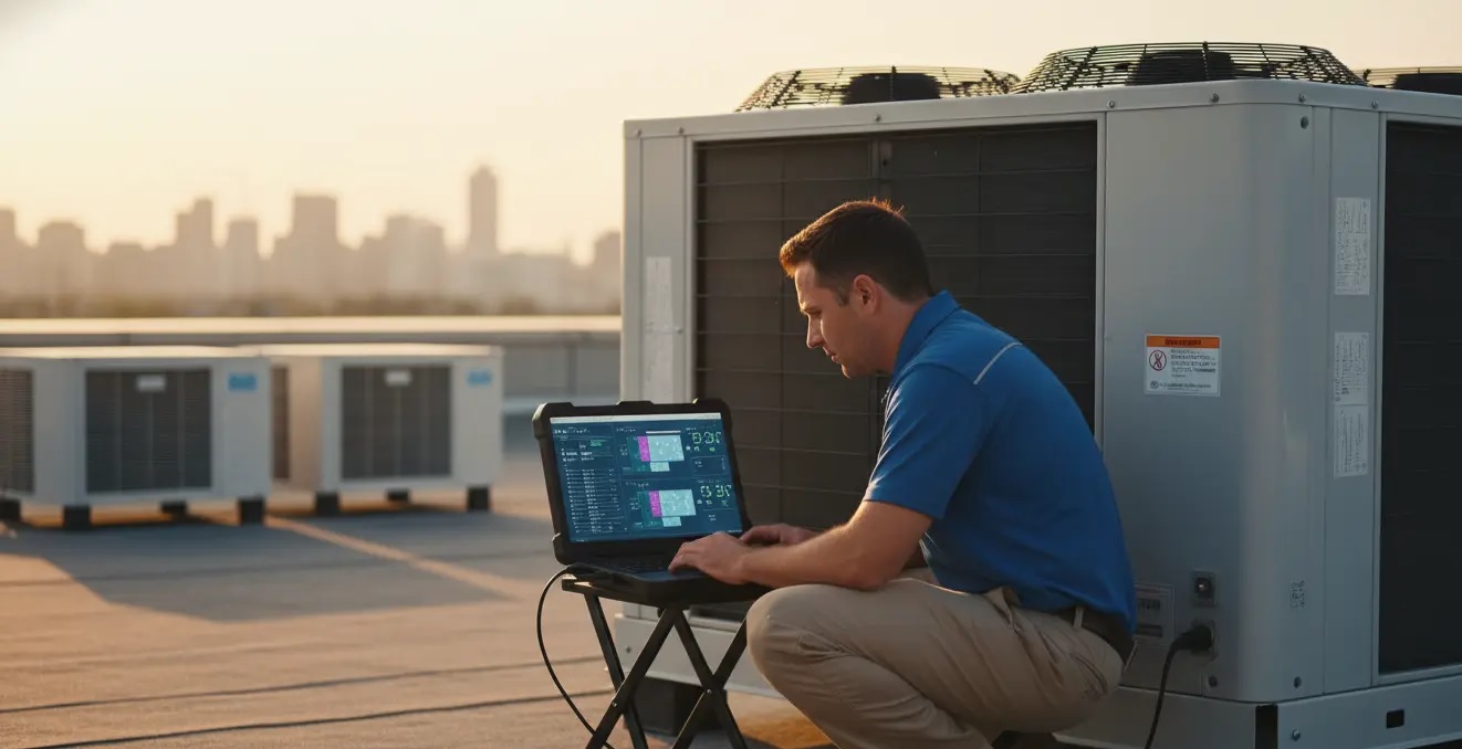
A professional technician does not guess — they diagnose. The correct diagnosis methodology relies on a logical sequence from symptoms to root cause, saving time and money and preventing fault recurrence.

The 5-Why Methodology for Root Cause Analysis
A Toyota fault analysis tool — applied by repeatedly asking "Why?" until reaching the real cause:
Example: Water-cooled chiller shutdown
- Why did it shut down? — Condensing pressure exceeded the allowable limit
- Why did pressure rise? — Water flow through the condenser decreased
- Why did flow decrease? — Lime scale deposits blocked the heat exchanger
- Why did deposits form? — Water treatment system was out of service for 3 months
- Why was it out of service? — No periodic maintenance schedule for water treatment ✅ Root cause
Water-Cooled Chiller Faults: Most Common
Fault 1: High Discharge Pressure
| Possible Cause | Diagnosis | Repair |
|---|---|---|
| Lime scale deposits in condenser | High ΔT across condenser (>5°C above normal) | Chemical Descaling with EDTA |
| Low water flow | Flowmeter measurement | Check pump + open valves |
| High condenser water temperature | Measure CW supply | Check cooling tower + water treatment |
| Refrigerant overcharge | High subcooling reading | Recover excess refrigerant |
| Non-condensable gases in system | High pressure even at low temperature | Purge and recharge |
Fault 2: Low Suction Pressure
| Possible Cause | Diagnosis | Repair |
|---|---|---|
| Refrigerant leak | Electronic detector + high superheat reading | Leak detection + repair + recharge |
| Stuck expansion valve | Very high superheat | Inspect and adjust TXV/EEV valve |
| Evaporator coil freezing | Very low temperature + reduced airflow | Defrost + check defrost sensor |
| Low chilled water flow | Measure CHW flow | Check CHW pump + valves |
Common VRF System Faults
| Error Code | Description | Most Common Cause | Repair |
|---|---|---|---|
| E1 / P1 | High pressure | Dirty or blocked condenser | Clean + increase airflow |
| E3 / P4 | Low pressure | Refrigerant leak | Leak detection + repair + recharge |
| E6 | Communication error | Damaged or loose data cable | Inspect and tighten RS-485 connections |
| U0 | Low refrigerant | Chronic slow leak | Comprehensive nitrogen test |
| H6 | Fan motor fault | Burnt or seized motor | Replace motor |
| F1 | Temperature sensor fault | Open or short circuit in sensor | Replace thermistor |
| AL | Phase loss | Overcurrent or missing phase | Check electrical system |
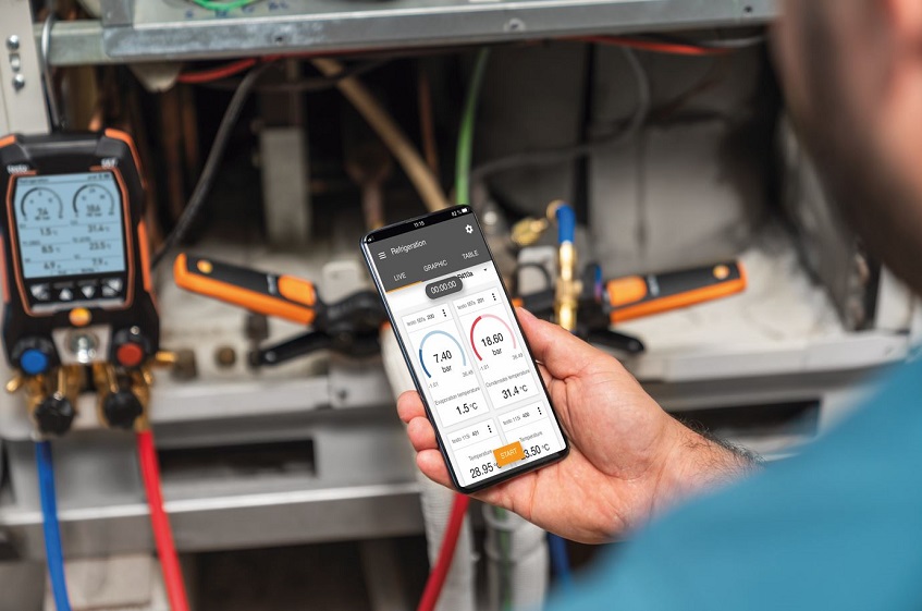
Electrical Fault Diagnosis: Essential Tools
- Digital Multimeter (CAT III 600V): Measure voltage, current, resistance
- Megohmmeter (1000V DC): Measure cable insulation resistance
- Thermal Imaging Camera (IR): Detect hot spots and faulty breakers
- Power Quality Analyzer: Detect harmonics and voltage imbalance
- Loop Tester: Measure short-circuit loop resistance
Infrared (IR) Thermal Scanning Procedure
One of the best predictive maintenance tools. A hot spot >30°C above normal = warning, >60°C = immediate danger.
| What is inspected | Normal indicator | Critical indicator |
|---|---|---|
| Busbar connections | ΔT < 5°C | ΔT > 30°C |
| MCCB/ACB breakers | ΔT < 10°C | ΔT > 40°C |
| Connection cables | ΔT < 5°C | ΔT > 20°C |
| Voltage transformers | ΔT < 30°C | ΔT > 50°C |