What are VRF/VRV Systems?
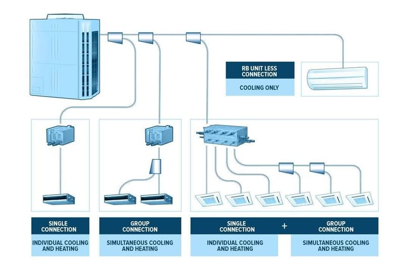
Variable Refrigerant Flow / Variable Refrigerant Volume systems are the latest generation of commercial air conditioning systems. They rely on a single external compressor (or a group of compressors) that precisely controls the amount of refrigerant reaching each indoor unit independently, achieving exceptional energy efficiency and superior thermal comfort.
Japanese company Daikin developed this technology in 1982 under the name VRV (Variable Refrigerant Volume), while other manufacturers used the name VRF. The difference is purely marketing — the technology is identical.
Engineering Principle of System Operation
The system operates on an optimized vapor compression cycle with:
- Multi-stage Inverter compressor: Adjusts its speed between 30-120 Hz to provide the precise required flow
- Electronic Expansion Valve (EEV): Allows control of refrigerant flow to each indoor unit with an accuracy of ±0.5 tons of refrigeration
- RS-485 communication protocol: Digital data network connecting the outdoor unit to all indoor units
Engineering Design Steps
Step 1: Cooling Load Calculation
According to the ASHRAE Handbook of Fundamentals using the CLTD/CLF method:
- External loads: Solar radiation through walls, roofs, and windows
- Internal loads: Equipment + lighting + people (75W sensible + 55W latent per person)
- Ventilation loads: Fresh air according to ASHRAE 62.1
| Load Element | Typical Value | Standard |
|---|---|---|
| External wall 20cm | 45-65 W/m² | ASHRAE 90.1 |
| Insulated roof (XPS 10cm) | 15-25 W/m² | ASHRAE 90.1 |
| Double Low-E glazing window | 180-280 W/m² | NFRC |
| Commercial LED lighting | 10-15 W/m² | IESNA |
| People (office) | 130 W/person | ASHRAE 55 |
Step 2: System Capacity Selection
After calculating the total load, the Connection Ratio (CR) is calculated:
CR = (Total indoor unit capacities) ÷ (Outdoor unit capacity) × 100%
Most manufacturers allow a CR between 50% - 130%, enabling 30% savings in outdoor unit cost.
Step 3: Refrigerant Piping Network Design

- Maximum pipe length: 165 meters (from compressor to farthest unit)
- Elevation difference between outdoor and indoor units: up to 50 meters
- Material: Dehydrated copper conforming to ASTM B280
- Silver soldering is prohibited — only phosphorus-copper soldering is used
Operational Specifications and Commissioning
- Pressure Test: 4.15 MPa with dry nitrogen for 24 hours
- Vacuum Drying Test: Reach -755 mmHg for 2 hours
- Refrigerant Charging: R410A or R32 per manufacturer specifications
- Control Parameter Adjustment: Evaporation temperature, superheat level
- Balancing Test: Verify performance of each indoor unit
Efficiency Comparison with Conventional Systems
| Parameter | VRF System | Chiller + AHU | Conventional Split |
|---|---|---|---|
| Coefficient of Performance (COP) | 4.5 – 6.0 | 4.0 – 5.5 | 2.5 – 3.5 |
| IPLV (Part Load Efficiency) | 7.0 – 9.0 | 6.0 – 7.5 | 3.0 – 4.0 |
| Installation cost/m² | Medium | High | Low |
| Control flexibility | Excellent | Good | Limited |
| Mechanical room space | Very small | Large | Not required |
PowerEM's Notable VRF Technology Projects
PowerEM has executed over 35 projects using VRF/VRV technology in recent years, most notably:
- Government office complex with 120 indoor units — Daikin VRV IV
- 5-story boutique hotel, 45 rooms — Mitsubishi Electric City Multi
- Specialized medical center — Samsung DVM S2 with 96 tons of refrigeration capacity